Executive Summary
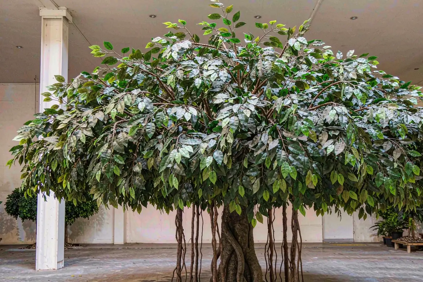
An 8 m artificial banyan on an exposed rooftop garden meets roughly 1.2 kPa of ultimate wind pressure at a 45 m/s three-second gust. With 7–9 m² of projected canopy and a drag coefficient near 1.2, that resolves to 10–13 kN of horizontal force and 40–55 kN·m at the base plate. The fixing decides compliance, not the foliage.
1. Failure Modes & Commercial Pitfalls
The fixing is nobody's line item until something moves. On a typical rooftop landscape package, four parties touch the anchor detail and the load case falls between them. The landscape architect sets the position and assumes an exposure. The structural engineer checks the slab for the planting load and stops there. The waterproofing specialist protects the membrane wherever a fixing penetrates it. The installation contractor sets, aligns and torques what somebody else specified. A supplier quotation that reads "fixing by others" is technically honest and commercially useless: it transfers a design obligation to a party that never priced it. The gap surfaces at handover, when the consultant asks for the calculation behind the base plate and no one in the chain owns the number.
A wind speed on a datasheet is not a design. Suppliers routinely quote a rating such as "suitable for wind speeds up to 40 m/s". Without the projected area, the drag coefficient and the height of the resultant above the base, that figure cannot be converted into a force, and two trees carrying the same label can differ by a factor of two in base moment because one has a fuller crown. The number that matters is not the wind speed the tree survives. It is the moment the anchor group is asked to resist at the site the tree actually stands on, at the height it actually stands at.
Rooftops are not ground-level sites with a better view. Wind speed rises with height above the surrounding terrain, and a parapet does not shelter a canopy that stands above it. At the corner of a roof, and along a parapet where flow separates, local speeds commonly run 1.3–1.5 times the value at the middle of the deck, and the pressure on a canopy that overhangs the edge is often suction rather than push. A base plate designed for the sheltered middle of a plant room roof, then installed at the exposed corner because that is where the architect wanted the tree, is a different structure with the same drawing number.
Ballast is assumed to be enough because it is heavy. A ballasted base avoids penetrating the membrane, which is why it gets chosen late in the programme. Weight resists overturning only through a lever arm, and it resists sliding only through friction, which for a steel plate on a protected membrane or paving is commonly taken at 0.4 or lower. A 7 m banyan generating 45 kN·m needs roughly 5 tonnes of ballast inside the footprint of its own base to hold that moment with a working margin, before any allowance for the canopy acting as a sail. A 300 kg planter with a concrete infill does not come close, and nothing on the drawing says so.
Value engineering quietly changes the capacity. Substituting a cast-in anchor with a chemical anchor, or a wedge anchor with a drop-in, or M20 with M16, or hot-dip galvanising with zinc plating, can remove 30–50% of the tension capacity of the group while the base plate drawing still reads the same. Each substitution looks trivial in isolation and none of them is re-checked against the wind case, because by that stage the calculation, if one exists, has already been issued.
Handover leaves no evidence. Year three is when the question gets asked: was the anchor torqued, to what value, into what slab, and by whom. Without a fixing record — anchor type, embedment, torque, photograph of each plate before the finish went down — the answer is a conversation rather than a document. That matters when a storm event, an insurance review or a defect liability period puts the installation under scrutiny, and it matters more on a rooftop, where the cost of a repair includes removing and reinstating the waterproofing above a live ceiling.
2. Material Science & Structural Engineering Standards
Start from the load path, not the product. Force enters at the leaf surface, passes through branch collars into the core tube, down the core into the base plate, through the anchor group into the slab. Every joint in that chain is a place where a nominal specification can be met on paper and still produce movement on site. A tree is a bluff body with a high surface-area-to-mass ratio, so the governing case is almost always lateral, and it is almost always expressed as a base moment rather than a weight.
Establish the design wind speed for the location and the height. Gulf coastal sites are usually specified with a basic three-second gust in the region of 42–45 m/s at 10 m over open terrain, then adjusted for the return period the client has bought and for height above grade. A tree standing 30 m up on a podium is designed for a higher speed than the same tree at grade, and the adjustment is not linear. Exposure category matters as much as the base value: the same 45 m/s produces materially different pressures over open coastal terrain and over a dense urban block, and the terrain that surrounds the building today may not be the terrain that surrounds it in ten years.
Convert pressure into force with numbers you can defend. Dynamic pressure follows 0.5 × air density × velocity squared, so 45 m/s at 1.2 kg/m³ gives about 1.22 kPa. Multiply by a drag coefficient and by the projected area of the canopy normal to the wind. A dense banyan crown with a solidity ratio in the region of 0.4–0.6 behaves closer to a solid body than to an open lattice, which is why a coefficient around 1.0–1.4 is the working band rather than the lower values used for bare frameworks. Eight square metres of projected canopy at 1.2 kPa and a coefficient of 1.2 is 11.7 kN, and applying that at a resultant height of 3.5 m gives about 41 kN·m. Those three numbers — pressure, force, moment — are what the anchor group must be checked against, and they are the three numbers a supplier quotation usually omits.
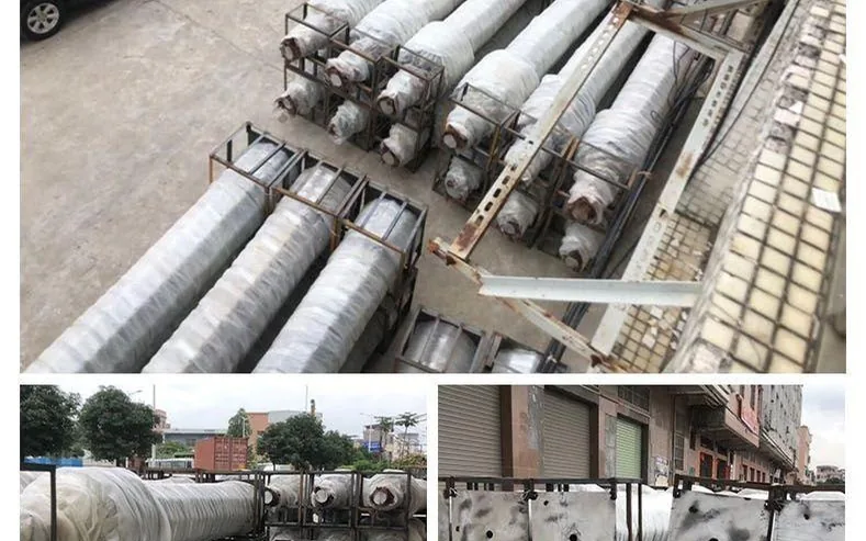
Size the core for the moment, then check it again for deflection. Above roughly 6 m, the structural question stops being the weight of the tree and becomes the bending at the base of the core. A Q235 hot-dip galvanised tube to ISO 1461, Ø60–76 mm with 2.5–3.0 mm wall, is the usual band for specimens in the 6–10 m range, with the diameter following the canopy sail area rather than the height alone. Continuous welds at branch collars matter more than nominal wall thickness, because a chain of tack welds creates the stress risers that appear later as a leaning trunk. Ask for the weld procedure and the inspection record, not only a mill certificate for the tube. Deflection is a separate check: a core that is strong enough but too slender will flex visibly in a gust, and a canopy that oscillates reads to occupants as instability regardless of the safety factor.
Match the base plate to the anchor group it will carry. Plate thickness of 12–20 mm with gussets back to the core is normal at this scale, and the plate has to be stiff enough to distribute tension into all four or six anchors rather than prying on two of them. Bolt spacing sets the internal lever arm, and a wider group reduces the tension per anchor for the same moment. That is why a plate drawn at 500 mm centres and a plate drawn at 700 mm centres are not interchangeable, even when both carry four M20 anchors.
Specify the anchor by substrate, then prove it. Cast-in anchors set during the slab pour give the most predictable capacity and the cleanest load path. Chemical anchors approved for cracked concrete are the practical choice for a retrofit, provided the embedment suits the slab depth and the edge distance is at least 1.5 times the effective embedment; a group drilled close to a slab edge or an opening loses capacity faster than most drawings assume. Concrete cone failure, not steel failure, is often the governing mode in a 150–200 mm slab, which is why the check belongs to the structural engineer of record rather than to the installer with a drill. Proof loading a sample of the installed group to 1.5 times the design tension, and recording the result with the torque values, converts the detail from an assumption into evidence.
Corrosion protection is part of the structural specification. Hot-dip galvanising to ISO 1461 at 85 µm or more is the baseline for the plate and the core on an inland site. Coastal rooftops with salt-laden air push the anchor and any exposed fastener towards 316 stainless, with isolating washers between dissimilar metals to stop bimetallic corrosion at the interface. A galvanised plate bolted down with plated steel anchors is a five-year detail on a twenty-year installation, and the failure shows up as rust staining on the roof finish long before anything moves.
Foliage density is a structural variable, not only a visual one. At 1,800 leaves/m³ a crown reads sparse from six metres away; at 3,200 it reads full and blocks sightlines. The same increase raises projected area, and projected area is a direct multiplier on force. A project that upgrades foliage density for realism after the base plate has been sized has changed the load case without changing the drawing, which is the quietest way to overspend a structural allowance. On an artificial banyan built to order, the density is a production instruction, so it can be fixed early; the plate schedule should follow it rather than precede it.
3. Life Safety, Fire Codes & Environmental Compliance
Overturning is a life-safety issue before it is a warranty issue. A tree that falls on a rooftop terrace can leave the building, land on a podium below or block a means of escape. That is why the reviewer treats an 8 m specimen as a non-structural element with structural consequences and asks for the calculation rather than a product certificate. In Saudi Arabia the conformity route for the imported product runs through SABER, and in the UAE public assembly interiors typically require the material test report, the installation method statement and the fixing design to be reviewed together. None of those documents can be produced retrospectively once the container has arrived.
Fire performance and fixing design are reviewed by the same consultant. Canopy foliage in a roof-level hospitality area is assessed as an interior finish with a fuel load. North American packages reference NFPA 701, with Method 1 for fabrics and Method 2 for materials that cannot be tested vertically; European and most GCC tenders reference EN 13501-1, where B-s1, d0 is the band commonly demanded for a feature tree in an occupied space. Ask for the report to name the method and the compound code, because a certificate issued for a different formulation says nothing about the canopy that ships. The fixing detail enters the same review: a penetration through a roof assembly has to preserve the fire separation as well as the waterproofing.
The canopy has to stay clear of the services it shares the roof with. Sprinkler throw, smoke exhaust inlets and detection coverage are designed around an unobstructed volume. A canopy that grows into that volume after the design freeze changes the performance of the system without triggering a review. On a roof deck the coordination is usually geometric — height of the tree against the height of the parapet, the plant screen and the exhaust louvres — and it is settled on a section drawing rather than on site.
Inspection is a scheduled activity, not a reaction to damage. A workable regime for an exposed rooftop is a visual check at twelve months covering plate, anchors, grout and membrane upstands, a torque verification sample at twenty-four months, and a documented inspection after any named storm event. If the specification allows the canopy to be removed ahead of a severe event, that decision needs a written procedure and a storage location, because a canopy taken down in an emergency and left on the deck becomes the debris the wind was going to remove anyway.
4. Technical Comparison Table
| Tree Height (m) | Min Core Steel Ø (mm) | Leaf Density (leaves/m³) | Design Base Moment at 45 m/s (kN·m) | Fixing Approach | Application |
|---|---|---|---|---|---|
| 4 | 48 | 2,200–2,400 | 10–14 | 4 × M12 chemical anchor, or 1.5–2 t ballast where no penetration is permitted | Seaside resort terrace, low parapet |
| 5 | 60 | 2,400–2,600 | 18–22 | 4 × M16 cast-in sleeve, 180 mm minimum slab | Corporate HQ roof garden, sheltered bay |
| 6 | 60 | 2,600–2,800 | 26–32 | 4 × M16 chemical anchor at 1.5 × embedment edge distance | Podium deck of a mall, planted edge zone |
| 8 | 76 | 2,800–3,000 | 40–55 | 6 × M20 cast-in, or through-bolt with spreader plate in a 200 mm slab | Rooftop garden of a 5-star hotel, exposed corner |
| 10 | 89 | 3,000–3,200 | 70–90 | Engineered base frame, 8 anchors, engineer-of-record sign-off on slab punching | Airport VIP lounge roof terrace, coastal podium |
Values assume a three-second gust of 45 m/s at the reference height, a drag coefficient of 1.0–1.4 and a projected canopy area consistent with the density band shown. Heights are overall installed height including the crown. Ballast figures are indicative only and must be checked against friction and slab capacity.
5. Structural Anchoring & MEP Coordination
Three fixing strategies, and the programme each one demands. A cast-in anchor group is the lowest-cost and most predictable option, and it only exists if the plate detail is frozen before the slab pours; changing it later means either a chemical anchor into a finished slab or a core-drilled through-bolt. A chemical anchor group is the retrofit route, and its capacity depends on embedment, hole cleaning, concrete strength at the date of installation and edge distance — all of which need recording, not assuming. A ballasted base avoids the membrane entirely, and it shifts the engineering problem from tension in steel to weight, footprint and slab loading, which is a different calculation rather than an easier one. A smaller specimen in the same family, such as a ficus canopy tree, reduces the moment but does not change the method.
The membrane detail is where a structural fix becomes a building defect. Any penetration through a roof waterproofing system needs a designed detail: a cast-in socket set with a proprietary flange, a protection board over the membrane around the plate, and a flashing that allows movement without tearing. Drilling through a finished membrane and sealing around the bolt with mastic is the detail that produces a ceiling stain eighteen months later, usually in a room with a fit-out that cost more than the tree. Where the specification forbids penetration altogether, the design moves to a ballasted or framed base, and the slab is then checked for the concentrated load of that ballast rather than for anchor tension.
Coordination points that decide whether the tree can be installed as drawn. Irrigation lines and lighting conduits crossing the planting zone need to be located before the plate position is fixed, because a plate that lands on a conduit is a plate that gets moved on site. Drainage outlets and overflow weirs set the minimum height of any ballast frame, and ponding around a base is both a membrane risk and a corrosion risk. Where the roof also carries condensers or a plant screen, the wake from those obstructions is part of the local wind environment, and a tree placed immediately downstream sits in turbulence that no code table describes.
A sequence that produces evidence, not just an installation. Set out the plate positions against the structural grid, not against the finished paving; cast in or drill and set the anchors with the type and embedment recorded; photograph each plate before the finish is laid; install the tree, shim and grout the plate, torque to the specified value and mark the fasteners; then file the torque record with the calculation and the product certificates. That file is the handover document. On projects with several roof levels, the detail usually changes between them, and a single generic method statement is the usual reason the exposed level is the one that fails inspection.
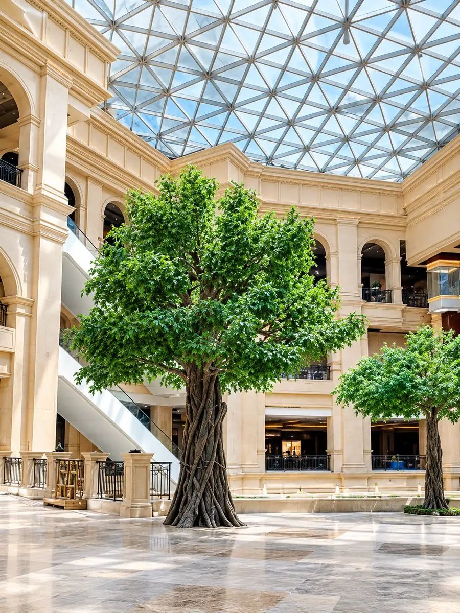
The same logic applies indoors, one level down. A hotel atrium tree does not see wind, but it sees the same scope gap: the plate is specified by one party, the slab checked by another, and the anchor installed by a third. On a suspended slab the governing check becomes punching shear around the plate rather than tension in the anchor, and the engineering calculations that close it are the same three numbers — pressure or imposed load, force, and moment or concentrated load. Where a canopy stands in a glazed commercial atrium with a high-level air curtain, the lateral load case is the air stream rather than the weather, and the plate still has to be checked for it.
6. Commercial Contractor FAQs
Q: Can the tree supplier issue the wind load calculation for the project?
A: The supplier can and should issue the inputs: overall height, canopy projected area at the specified density, total mass, centre of gravity and the base plate geometry with bolt spacing. The site-specific calculation — design speed, exposure, topography, slab capacity — has to be stamped by the engineer of record for the building, because it depends on information the supplier does not hold. A supplier document presented as a structural calculation is a datasheet with a title block.
Q: Is a 300 kg ballast base enough for a 6 m tree on an exposed roof?
A: Almost never. A 6 m specimen at 45 m/s develops roughly 26–32 kN·m, and ballast resists that through half its footprint width, so a 1.2 m base needs on the order of 5 tonnes to hold the moment with margin, plus friction against sliding. Weight below that figure may still be adequate in a sheltered courtyard between wings, which is exactly why the exposure assumption has to be written down rather than implied by the choice of base.
Q: What test actually proves the anchors are right?
A: A proof load on a sample of the installed group, taken to 1.5 times the design tension and held long enough to observe movement, with the result recorded against the anchor type, embedment and torque value. Where proof loading is impractical on the finished installation, a pull-out test on a mock-up in the same slab build-up, plus a documented torque regime for every fastener, is the accepted substitute. Neither replaces the calculation; both make it verifiable.
Q: Does a rooftop really need a different wind speed from the same tree at ground level?
A: Yes. Speed increases with height above the surrounding terrain, and local acceleration at corners and parapets adds a further factor that is commonly 1.3–1.5. A tree approved for a plaza at grade and re-specified for a thirtieth-floor terrace is carrying a higher pressure, a longer moment arm and often a more exposed position, so the plate detail that worked at grade is not the same detail.
Q: How long does the calculation and approval add to the programme?
A: The engineering itself is short — days, not weeks — once the site data, the canopy area and the slab information are available. The delay sits in collecting those three inputs from three different parties. Projects that freeze the plate position before the slab pour typically absorb the work inside the normal drawing programme; projects that order the tree first and ask the structural question afterwards add a retrofit, a chemical anchor design and a membrane detail to the critical path.
Project Engineering Support & CAD Requests
We issue the structural inputs pack with every large specimen: canopy projected area at the specified leaf density, mass and centre of gravity, base plate geometry with bolt spacing, and the plate drawing in DWG so your engineer of record can run the site-specific check without redrawing the detail. For rooftop and podium projects we also supply the recommended anchor type by substrate and the torque values we expect to see at handover. Send the terrace layout, the parapet height and the slab build-up, and we will return the plate schedule and the fixing scope split in writing, so the quotation does not leave the anchor to nobody.
👉 Chat with Structural Engineering on WhatsApp (Instant Project Review)